NXU-2A : User Manual
Network Extension Unit
Revision 0.5 July 11, 2016
Designed and Manufactured by:
JPS Interoperability Solutions Inc.
5800 Departure Drive
Raleigh, NC 27616
http://www.jpsinterop.com 919-790-1011
NOTICE
JPS Interoperability Solutions Inc. reserves the right to make changes to the equipment and specifications without prior notice.
PROPRIETARY STATEMENT
The information contained in this manual is the property of JPS Interoperability Solutions Inc and is intended for the purchaser’s use only. It may not be reproduced without the express written consent of JPS Interoperability Solutions Inc.
General Information:
This subset of the instruction manual provides the information necessary to install and operate the NXU-2A Network Extension Unit.
NXU stands for Network Extension Unit. NXU units connect communications equipment to a digital network using VoIP (Voice over Internet Protocol) technology. NXU units use JPS’ proprietary technology, embodied in a family of hardware and software products that enable voice communications devices to be interconnected via a network across the room or around the world. Voice over Internet Protocol, known as VoIP, is a means of digitizing voice signals and transmitting them over a digital network, such as a LAN, WAN or even the Internet itself.
The NXU technology enables the design of low cost, extremely flexible radio communications networks.
It multiplexes voice audio and data over a standard Ethernet network, uses existing network infrastructure eliminates the need for leased lines and microwave sites, eliminates the requirement for pilot tones and other in-band signaling and facilitates centralized control of a communications network from a single computer.
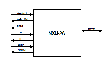
The NXU-2A is intended for use with radio communications consoles, communications radios, and JPS products such as the ACU-1000 Interconnect Unit. A general-purpose stand-alone device interfaces full duplex audio, one RS-232 port, and three status bits onto an Ethernet network. A pair of NXU-2As can form a simple system that creates a transparent communications link between the two. The NXU-2A at one end (usually the equipment end) is the server; the one at the other end (usually the operator end) is the client. The audio, RS-232, and status bits are transparently transferred between the server and the client.
Any NXU-2A can be set up as a server or as a client depending on system needs. The RS-232 interface allows for different baud rates between the server and the client.
The NXU-2A monitors its network connection and adjusts its parameters automatically to provide optimum performance under varying network conditions. Front panel indicators display the unit’s status. Initial configuration is done through the NXU-2A’s serial port, but following this initial setup, a standard web browser can be used over the network to view and change the unit’s settings and also to perform diagnostic tests.
Designed for years of continuous operation in mission-critical applications and remote locations, the NXU-2A has no moving parts and requires no periodic shutdown or maintenance. Start up upon power on is typically 5 seconds.
The NXU-2A is a 10BASE-T Ethernet device and each unit has a unique Ethernet address and an RJ-45 physical interface jack. A 10BASE-T device operates at 10 Mbps and interconnects to a hub (star topology) using standard CAT 5 twisted pair cable, also known as UTP. The maximum cable length between an NXU-2A and its hub port is 100 meters. With the right connective equipment (recommended or supplied by JPS), the NXU-2A’s Ethernet port can be linked with virtually any LAN, WAN, or the Internet, no matter which topology or cabling system is in use.
|
RX Audio Input |
|
|
Input impedance |
Balanced 47k ohms, transformer coupled. |
|
Input Level |
Incoming signals adjustable from –30 to +11 dBm to set 0 dBm nominal input; +15 dBm clipping. +20db boost configurable |
|
Frequency Response |
10 Hz to 3600 Hz +/- 2dB. |
|
TX Audio Output |
|
|
Output Impedance |
Unbalanced 10 ohms, AC Coupled. |
|
Output Level |
Adjustable from –30 to +11 dBm, 0 dBm nominal factory default; +15 dBm clipping into a 600 ohm load. |
|
Frequency Response |
10 Hz to 3350 Hz +/- 2dBm. |
|
Distortion |
0.5% or less (excepting Vocoder). |
|
COR & AUX Input |
|
|
Input impedance |
47k ohm pull-up to +5V. |
|
Polarity |
COR: Selectable active low ,active high,VOX,VMR; AUX Inputs: Active low. |
|
Threshold |
+2.5V nominal. |
|
Protection |
Up To + 100 VDC. |
|
PTT and AUX Output |
|
|
Output Type |
Open drain, 47k ohm pull-up to +5V. |
|
Maximum Sink Current |
100 mA. |
|
Max Open Circuit Voltage |
+60 VDC. |
|
Serial Interface |
|
|
Interface Type |
RS-232, Asynchronous, Full Duplex. |
|
Baud Rates |
300, 1200, 2400, 4800, 9600, 19200, 38400, 57600, 115200 bps. |
|
Connector |
DB-9 Male, Standard PC/AT DCE Pinout. |
|
Network Interface |
|
|
Interface Type |
10BASE-T Ethernet, 10Mbps; RJ-45 Connector. |
|
Protocols |
Audio and status-UDP, RS-232- TCP. |
|
Audio Vocoder |
Selectable, 13, 16, 24, 32, or 64 Kbps data rate. |
|
General/Environmental |
|
|
Programming/Configuration |
Web, Telnet, or RS-232 Interface. |
|
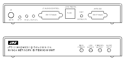
Front Panel |
Power, Link Active, Channel Active, and Audio Level LEDs. |
|
Rear Panel |
Audio/Data, Serial, Network, and Power Connectors. |
|
Audio/Data Connector |
DB-15 Female. |
|
Input Power (12 VDC Nom) |
+11 to +15 VDC @ 0.5A max. 12VDC (Wall-cube supplied). |
|
Power Connector |
Coaxial Jack, 2.5 mm ID, 5 to 5.5 mm OD; Center Pin Positive; Reverse Polarity Protected. |
|
Size and Weight |
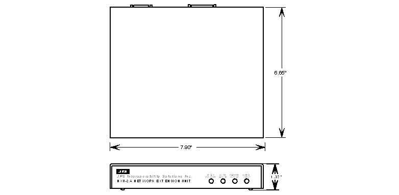
1.7” H x 7”W x 9”D (4.3 x 17.8 x 22.9 cm). 4lbs. (1.8kg). |
|
Temperature |
Operating: -20 to +60 degrees C. Storage: -40 to +85 degrees C. |
|
Humidity |
Up to 95% @ 55 degrees C. |
|
Shock |
MIL-STD-810D, Method 516.3, Procedure VI. |
|
Vibration |
MIL-STD-810D, Method 514.3, Category 1. |
Careful attention to the following installation suggestions should result in the best unit/system performance.
The NXU-2A must be installed in a structure that provides both protection from the weather and assurance of ambient temperatures between -10 and +55 degrees C. Since the unit is neither splash proof nor corrosion resistant, it must be protected from exposure to salt spray. When the unit is mounted in a cabinet with other heat-generating equipment, the use of a rack blower is suggested to keep the cabinet interior temperature rise to a minimum.
NOTE: If the NXU-2A is installed in a high RF environment such as repeater system orother transmitter site, it is recommended that all cable assemblies be individually shielded, with the shield grounded to the ground pin on the terminal block for that module. For all D-subminiature connector cable assemblies, cable shields should be connected to connector shells so that they make contact with the grounded D-subminiature connector shells on the NXU-2A.
NOTE: Do not exceed 15VDC input to the NXU-2A. The NXU-2A contains a 15V zener diode across the DC input to protect internal circuits from transient over voltage. Attempting to power the NXU-2A from a constant DC source that delivers more than 15V may damage the zener diode and/or other components and render the unit inoperative
NXU-2AControl and Connector Locations
Internal Configuration
The illustration below shows the NXU-2A with its top cover and rear panel removed. There is normally no reason to remove the top cover, as the NXU-2A has no internal user-serviceable configuration controls.
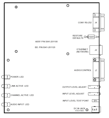
NXU-2A Internal View
The NXU-2A is designed to operate from a nominal +12V DC supply. The unit will meet all of its specifications over a voltage range of +11 to +15 VDC. The DC power consumption is 500 mA maximum. The AC adapter provided with the unit meets these specifications. To power the unit from another +12V DC source, a 2.1mm I.D. coaxial power plug will be required to connect the power source to J6 on the NXU-2A rear panel. The center conductor is positive (+).
The NXU-2A is a microprocessor-controlled device. As with any such equipment, a very short loss of power can cause operational problems and/or cause the unit to reset. The communications link will be inoperable during the reset period. JPS recommends the NXU-2A and associated equipment be connected to an AC power source that utilizes an uninterruptible power system (UPS). If the overall site does not have UPS capability, the NXU-2A should be plugged into a smaller UPS, such as those used for personal computer systems.
The NXU-2A operates on a nominal +12 VDC. The power is applied through J6 via the “Wall Cube” AC adapter provided with the unit, or through a 2.1mm I.D. coaxial plug.
Audio Level Adjustment Potentiometers and Input Test Point
A test probe may be inserted into the test point to measure the level of the incoming audio.
Connection to Radio or Other Four-Wire Device (J7)
The interface between the NXU-2A and associated radio or other audio device is made via J7 (Audio/Control) on the rear panel. J7 is a female DB-15 connector.
|
PIN |
Signal |
Description |
|
1 |
Ground |
Ground connection. |
|
2 |
|
Not used. |
|
3 |
/AUX In 0 |
Auxiliary Input 0 - Active low. |
|
4 |
/AUX Out 0 |
Auxiliary Output 0 - Active low. |
|
5 |
Ground |
Ground connection. |
|
6 |
Audio Input |
Balanced audio input. |
|
7 |
Analog Ground |
Analog ground. |
|
8 |
Audio Output |
Unbalanced Audio output. |
|
9 |
|
Not used. |
|
10 |
/AUX In 1 |
Auxiliary Input 1 - Active low; general purpose. |
|
11 |
/AUX Out 1 |
Auxiliary Output 1 - Active low; general purpose. |
|
12 |
/COR Input |
Input from radio COR, programmable active high or low. |
|
13 |
/PTT Out |
Output to radio PTT, active low, open drain. |
|
14 |
Audio Input |
Balanced audio input. |
|
15 |
Analog Ground |
Analog ground. |
Network Connection, J3
The NXU-2A is connected to the Ethernet network via rear panel connector J3 using a standard RJ-45 Ethernet Patch Cable (non-crossover). A six-foot long cable is included with the unit.
Serial Port Connection, J4
J4 is a standard RS-232 DCE serial port. It is a female DB-9 connector, and can be interfaced to most PCs, typically standard DTE serial ports, using the DB-9 straight-through serial cable included with the NXU-2A.
|
J4 pin |
Description |
|
2 |
TX data |
|
3 |
RX data |
|
5 |
Ground |
Configuration:
This section explains all settings and level adjustments that configure the NXU-2A. It is not necessary to remove the NXU-2A cover to configure the unit.
Configuring an NXU-2A or pair of NXU-2As requires that you allocate an IP address for each unit, and that you designate one unit as a Client and one unit as a Server (explained in subsequent paragraphs). Initial configuration is accomplished by attaching a serial RS-232 terminal to J4. If the unit already has an IP address and is on a network, configuration may be done by connecting to the unit’s IP address via telnet or with a web browser. Each method of configuration is discussed below.
NOTE: The NXU-2A comes from the factory configured as a server with the following default settings:
IP Address: 192.168.1.200
Subnet Mask 255.255.255.0
Gateway IP 0.0.0.0
If the above network parameters are compatible with your network then you may attach the NXU-2A to your network and use your web browser or telnet client to configure the NXU-2A.
To configure the NXU-2A using the serial port, connect a standard serial cable from a suitable COM port on your PC to J4 on the NXU-2A rear panel. A standard DB-9 straight-through cable (which should work on most PCs) is included with the NXU-2A. The NXU-2A comes pre-configured with the serial port set at 9600-baud, 8 data bits, no parity, and 1 stop bit. No hardware flow control is used or needed. In order to configure the NXU-2A you will need to know which COM port you are connected to on your PC.
A terminal program is needed to communicate with the NXU-2A for initial configuration. A suitable Windows terminal program, MTTTY.EXE, is included with the unit or from the JPS web site at http://www.jpsinterop.com/customer-service/
With the serial cable connected and the PC running a terminal program set to the above parameters, apply power to the NXU-2A. Wait at least 10 seconds after power up of the NXU-2A and type +++ (three plus signs) on your keyboard. You must type all 3 ‘+’ characters within 1 second. Do not type anything else – only the 3 ‘+’ characters. The NXU-2A should respond with ‘OK’. At this point, you are in Command Mode, and you will be able to issue configuration commands to the NXU-2A.
NOTE: If you type the three plus signs into your terminal program and they appear on the screen, the NXU-2A is already in the COMMAND Mode.
Configuration Mode Command Set
Type HELP and press the ENTER key. The NXU-2A should respond with:
NXU-2A Commands:
BAUD BCAST CMDPORT CONMODE
CONN COR CORINH DATA
DISC DUPLEX ECHO GATEIP
HANGTM HELP MAC MYIP
NAME PARITY PASS PORT
REBOOT SAVE SECURITY SRVRIP
SRVRPORT STAT STOP SUBNET
TRAN VER VOCODER WHAT
BOOST RXDELAY TXDELAY VSENSE
Type HELP followed by a command to get help on that command.
Save changes with the SAVE command.
NOTE: If you decide that you don’t want to make any changes to the NXU-2A settings then you should place the NXU-2A back into the TRANSPARENT Mode. The TRAN command should be used to do this, placing the unit back into the data mode.
This is a full list of the commands available in the NXU-2A command mode. More detail is given on the following pages. You can get a one-line summary of each command by typing HELP followed by the command.
BAUD <rate> - Set the serial port baud rate
CONMODE <0/1> - Places unit in CLIENT (0) or Server (1) mode
CONN <IP address> - Connect this client to a server at IP address
COR <0/1/2> - Sets COR active low (0), high (1), or VOX (2)
CORINH <time> - Set COR inhibit time to 0,500,1000,2000,3000, or 4000 mS
DATA <7/8> - Set the serial port data bits
DISC - Break this client’s current connection
DUPLEX <0/1> - Select either full duplex (0) or half duplex (1) for audio
ECHO <ON/OFF> - Enables/disables character echo to console
GATEIP <ip address> - Set gateway IP address for this unit
HANGTM <time> - Set VOX hang time to 500,1000,2000,3000, or 4000 mS
MAC – Return the Ethernet MAC address of this unit
MYIP <ip address> - Set the IP address of this unit
NAME <text description> - Give this unit a name
PARITY <O/E/N> - Set the serial port parity to Odd, Even, or None
PASS <password> - Assign a password for web access
PORT <port number> - Set the IP port used by this unit
REBOOT - Restart this unit
SAVE - Save NXU-2A settings to FLASH memory and restart
SECURITY <security level> - Set the security level (0-255)
SRVRIP <ip address> - Set the IP address of the NXU-2A server
STAT - Return this client’s current connection status
STOP <1/2> - Set the serial port stop bits
SUBNET <ip address> - Set IP subnet mask for this unit
TRAN - Place this unit’s serial port in transparent mode
VER - Print the software version information for this unit
VOCODER <number> - Select the voice compression method (1-5)
WHAT - Print a description of this unit’s settings
BOOST <+20db input boost> - Select either no boost (0) or +20db (1)
RXDELAY <number> - Set the receive delay to NNNNN mSec
TXDELAY <number> - Set the transmit delay to NNNNN mSec
VSENSE <number> - Set the vox/vmr sensitivity: 0=low, 1=med, 2=high
The first thing you should do is to set the IP address of the unit. The NXU-2A comes from the factory with a default IP address set to 192.168.1.200. Set the address by typing:
MYIP <IP address>
Where <IP address> is the IP address of the unit in dotted quad notation. All configuration commands are entered by a carriage return. In this example, if your desired IP address is 192.168.1.1 you would type MYIP 192.168.1.1 and press ENTER
Setting Unit Subnet Mask and Gateway Address
Now set your subnet mask using the SUBNET command. If you are using a gateway, set the gateway address (the address of your router) using the GATEIP command. If on a LAN with no gateway, leave the gateway address set at the default address 0.0.0.0.
Using DHCP to Assign IP Parameters
If you have a DHCP server on your network, you may configure the NXU-2A to obtain its IP address, subnet mask, and gateway address via DHCP. Setting the NXU-2A IP address to 0.0.0.0 will cause it to attempt to contact a DHCP server on power-up. NOTE: Using DHCP is not recommended for NXU-2A Server units since the IP address assigned by the DHCP server is not generally known and is subject to change. If DHCP is to be used, it should only be used on client NXU-2A units.
Setting VoIP Port (Optional)
The default port used by the NXU-2A for the transport of audio across the network is 1221. Under normal circumstances, this should not be changed. The default port may be changed, if necessary, by using the PORT command. Type PORT <port number> and press ENTER to select a new default port. The port number must range from 1 to 65535.
Whether the unit will be a client (a unit which can make and break connections) or a server (a unit which only accepts connections from a client) will need to be decided. This selection is made with the CONMODE command. CONMODE 0 configures the unit as a client, while CONMODE 1 configures the unit as a server. For a client unit, you also need to set the IP address of the corresponding server with the SRVRIP command. For example, if a client unit is going to be connected to a server NXU-2A at address 192.168.1.10, then the command must be issued:
SRVRIP 192.168.1.10
On the client unit, if you do not want the client unit to connect to a server automatically at power-up then set the server IP address to 0.0.0.0 by typing SRVRIP 0.0.0.0
The NXU-2A uses the COR (Carrier Operated Relay) or equivalent signal from your radio to determine when to send audio data across the network. When the COR input is active, audio is transferred to the other side of the network. The COR command allows you to select the polarity of the COR input. If a COR output signal is not available, you may select VOX (Voice Operated Switching). VOX operation uses the detection of an audio signal from your radio or other audio device to control the flow of audio from the NXU-2A.
Select the polarity of the COR input by using the COR command. COR 0 selects active low COR, while COR 1 selects active high COR sense. COR 2 selects VOX mode. In VOX mode, no connection to the NXU-2A COR input is required, since the audio input level itself is used to determine when a signal is present. In order to conserve network bandwidth, digital audio packets are only sent when COR is active. If using the NXU-2A in an application where the connected equipment does not support the COR line, then the COR line must either be tied to its active state (in which case audio will be sent across the network continuously) or you must select VOX mode. In any case, the COR or VOX mode must be set properly since the NXU-2A uses this setting to determine when to send audio data across the network.
The NXU-2A allows full-duplex audio operation. Audio can be received and transmitted at the same time. In some applications this is required, but in other applications this may not be desirable. For example, if the system echoes back the transmitted audio to provide sidetone monitoring the resulting audio will be slightly delayed. Listening to a delayed version of your own voice can be distracting, and in such cases it would be better to use half-duplex audio. Use the DUPLEX command to set full- or half-duplex. DUPLEX 0 selects full-duplex operation (the default) while DUPLEX 1 selects half-duplex. NOTE: When half-duplex operation is selected the NXU-2A will not receive incoming audio while its COR or VOX is active.
When VOX mode is enabled, you may also adjust the VOX hang time. This is the amount of time the VOX remains active after the input signal falls below the VOX threshold, and may be set to 500, 1000, 2000, 3000, or 4000 milliseconds. This is useful to prevent the VOX from dropping out between words or syllables. Use the HANGTM command followed by 500, 1000, 2000, 3000, or 4000 to select the hang time. The factory default is 500 milliseconds.
In some applications it may be necessary to inhibit the NXU-2A’s response to the COR input (whether hardwired COR or VOX) for a brief period of time (and under certain circumstances) in order to avoid problems with the “ping pong” effect.
The “ping-pong” effect can occur when the COR output of a device is activated momentarily by the device when it switches out of the TX mode. There are varieties of reasons why this can happen (including squelch tails on some radios), and it may occur with COR or VOX, but the result is the same.
To illustrate the problem, assume that there are two radios connected over a network by a pair of NXU-2As. An active COR at one end of the network creates an active PTT at the other end. When the COR of Radio 1 is active, Radio 2 is transmitting, and vice versa. Consider what can happen when the switch out of the TX mode causes a momentary active COR output:
Radio 1 COR becomes deactivated, so the Radio 2 switches out of the TX mode and activates it’s COR output momentarily. This momentary Radio 2 active COR signal causes Radio 1 to switch momentarily to TX mode, and when it quickly drops back out of the TX mode its own COR output is momentarily activated. This will once again put Radio 2 in the TX mode, causing an endlessly repeated cycle where the radios “ping-pong” back and forth and in and out the TX mode.
The COR Inhibit feature prevents this problem by ignoring any active COR input that occurs just after the NXU’s TX output command is de-activated. The unit ignores the COR input (whether hardwired or VOX) only in the specified interval immediately following the inactivation of its PTT output. Use the CORINH command followed by 500, 1000, 2000, 3000, or 4000 to select the COR inhibit time in milliseconds. Type CORINH 0 to disable the COR inhibit feature. The COR inhibit time should be set as long as required to prevent the “ping-pong effect”, but no longer, or the beginning of a valid audio signal being transferred might be lost.
The serial port baud rate may be set using the BAUD command. Valid baud rates are 300, 1200, 2400, 4800, 9600, 19200, 38400, 57600, and 115200. The number of data bits may be programmed to 7 or 8 using the DATA command, while the number of stop bits may be programmed to 1 or 2 using the STOP command. The serial port parity may be programmed to odd, even, or none by typing the PARITY command followed by O, E, or N.
In order to send voice information over an IP network efficiently the NXU-2A uses digital signal processing algorithms to compress the voice information so that it requires less network bandwidth. The NXU-2A offers several different voice compression methods to support a variety of applications. For example, some compression methods work well with voice and provide a high amount of compression, but do not handle signaling tones very well. Other methods handle tones and voice, but use more network bandwidth because they offer less compression. You may select the method from the following voice compression schemes that optimizes the trade-offs for your particular application:
1. GSM 13Kbps - Suitable for voice communications only. Should not be used if any tone signaling is required. Offers the greatest compression with reasonable voice quality. This is the default setting.
2. ADPCM 16Kbps – Suitable for voice or tone signaling. Offers good voice compression, but the voice quality is lower than the other compression methods.
3. ADPCM 24Kbps – Suitable for voice or tone signaling. Offers less compression than ADPCM 16Kbps but the voice quality is higher.
4. ADPCM 32Kbps – Suitable for voice or tone signaling. Offers still less compression, but the voice quality is the best of the ADPCM compression types.
5. PCM 64Kbps – Suitable for voice or tone signaling. Offers the highest quality of all compression methods, but provides the least compression. You should use this method only if your network offers low latency and good throughput.
You may select a compression method with the VOCODER command followed by the number of the compression method (1-5). If you are only using voice in your application, you should select GSM 13Kbps (1). If you plan to use any tone signaling, you should select 2, 3, 4, or 5 in accordance with your network bandwidth and voice quality requirements.
The NXU-2A may be configured, monitored, and controlled remotely via its network interface using a web browser or a telnet client. In some instances, it may be desirable to limit access via one or both of these methods, or to selectively limit the things that may be done remotely. The SECURITY command allows various levels of security to be set in order to limit remote access. Additionally, a password may be assigned to limit access via a web browser. Refer to the user manual Security section for detailed information on setting the NXU-2A security parameters.
The Ethernet MAC address of the NXU-2A may be read using the MAC command. When MAC is typed the 48-bit Ethernet MAC address will be printed as a sequence of two digit hexadecimal numbers separated by dashes. No two NXU-2A units have the same MAC address, so this may be used as an electronic serial number if desired. It cannot be changed by the user.
Store Setup Changes with SAVE Command
After any configuration changes have been made, SAVE must be typed in order to store the new settings in memory. The NXU-2A will automatically restart after changes have been saved. If you do not make any changes and want to return the serial port to the data mode, type TRAN to place the serial port in transparent mode.
NXU-2A Extended Features:
Several new operating features have been incorporated into the NXU-2A which are a superset of the original NXU-2. These features are ONLY available in the NXU-2A and are NOT backward compatible with the original NXU-2.
Input Level Boost +20db: (new feature)
The receive input level may optionally be boosted by +20db in order to accommodate low level signal sources. Provisioning via the web interface allows selecting either “No Boost” or, “Boost +20db” in the ‘RX Boost Mode’ field.
TX Delay: (new feature)
Additional delay may provided to the transmit audio path. Via the web interface ‘TX Delay (mS)’ field, the user may introduce from 0 to 10 seconds of delay, in 100 mS increments. Upon editing the field with numeric data, the NXU-2A will round to the 100mS interval. When additional delay is used, the PTT\ signal will be asserted prior to the delayed audio being presented, such that LMR trunking systems may be accessed without audio loss.
RX Delay: (new feature)
Additional delay may provided to the receive audio path. Via the web interface ‘RX Delay (mS)’ field, the user may introduce from 0 to 10 seconds of delay, in 100 mS increments. Upon editing the field with numeric data, the NXU-2A will round to the 100mS interval. When additional delay is used, the received audio will be delayed before being sent to the network.
VMR: (new feature)
Voice Modulation Recognition has been added to allow interfacing with radios which do not provide a separate COR signal. VMR provides a more robust method of ‘COR Sensing’ than VOX alone. VMR mode may be selected via the web interface ‘COR Sense’ field pulldown menu. When VMR mode is chosen, the hardware COR signal is ignored, and audio content with the appropriate speech characteristics is allowed to simulate the COR signal.
VOX and VMR Sensitivity Adjustments: (new feature)
When either VOX or VMR COR sensing is selected, three levels of sensitivity adjustments are provided to allow greater flexibility. Via the web interface, “Low” sensitivity requires more signal content to recognize and simulate COR activity. “High” sensitivity requires less signal content to recognize and simulate COR activity. The default sensitivity is “Medium”.
Restoring Factory Defaults: (new feature)
The NXU-2A had added the capability to restore the original factory default operating conditions. This may be useful if the unit has been incorrectly configured, and it is necessary to return to a well defined state. To restore the factory default conditions, the power to the unit needs to be removed and restored while rear panel switch “SW1” (DEFAULTS) is depressed. When the front panel LED’s have blinked, the switch may be released, and the unit will be operational using the JPS factory default parameters. The IP address will return to “192.168.1.200”, which will allow web configuration. All other previously assigned user parameters will be lost during this process.
After the NXU-2A has been assigned a valid IP address and is on the network, you may configure it via telnet or a web browser. For telnet, use your PC’s telnet client to connect to the IP address of the NXU-2A. Once a telnet connection is made configuration of the NXU-2A is identical to configuration via the serial port as previously described, except that there is no need to type +++ to enter command mode. The telnet connection to the NXU-2A will automatically disconnect after two minutes of no activity. LOGOUT may also be typed to disconnect the telnet connection manually.
A web browser may also be used to browse the IP address of the NXU-2A. From the opening page select NXU-2A Configuration.
Three other web pages may be browsed to access “Connection Management”, “Connection Status”, and “Information”. Samples are show below. In addition, this subset of the user manual is browseable via the “Manual” page. For additional information, see the full user manual, available on the web at: http://www.jpsinterop.com/customer-service/
This section provides detailed explanations of the NXU-2A’s audio interfaces and its parallel control inputs and outputs.
The NXU-2A audio input is 47K ohm, balanced. It can be used as an unbalanced input by grounding one half of the balanced pair and connecting the single-ended input to the remaining half. The use of balanced inputs and shielded cables is recommended for superior immunity to noise.
The audio input will accept signal levels from –30 to +11 dBm. Internal circuitry is used to amplify or attenuate this input as necessary to optimize the level to the DSP. The signal level is adjusted by the IN LVL potentiometer accessible from the rear panel. The input is set to 0 dBm when shipped. This means the IN LVL potentiometer is adjusted so that an audio input of 0 dBm provides the correct level to the DSP circuitry.
Access to an audio test point, TP1, is provided via the rear panel so the actual audio signal voltage applied to the A/D converter can be measured with an AC voltmeter. The correct level for best operation as measured at TP1 is about 0.2V or –12dBm (600 ohm reference.)
The audio output from the NXU-2A is a low impedance (10 ohm) unbalanced AC coupled output. The output level is adjusted by the OUT LVL potentiometer accessible from the rear panel. This output provides a 0 dBm nominal level; +15 dBm clipping into a 600 ohm load. The audio output will supply signal levels from –30 to +11 dBm.
The COR input to the NXU-2A is a high impedance input and can be programmed to be active high or active low. In the active low configuration the input is pulled up to +5V DC internally through a 47K ohm resistor. In the active high configuration, the input is pulled down to ground through a 22K ohm resistor. The logic threshold is 2.5V DC nominal, and the input is protected from momentary surges up to +100 V DC.
The AUX inputs (AUX IN0 and AUX IN1) are high impedance inputs, and are always active low. They are pulled up to +5V DC internally through a 47K ohm resistor. The logic threshold is 2.5V DC nominal, and the input is protected from momentary surges up to +100 V DC.
The PTT output from the NXU-2A is an open drain type. It can sink up to 100 mA of current, and can withstand open-circuit voltages up to +60V DC. In order to avoid conflicts with internal pull-up resistors on the PTT lines of some radio equipment, there is no internal pull-up resistor on the NXU-2A PTT output.
The AUX outputs from the NXU-2A (AUX OUT0 and AUX OUT1) are open drain types. They can sink up to 100 mA of current, and can withstand open-circuit voltages up to +60V DC. These lines are pulled up to +5V DC through a 47K ohm resistor.
Front Panel Indicators
All front panel indicator LEDs are explained below, starting at the left side of the unit.
Power LED This yellow LED lights whenever DC power is applied to the unit.
Link Active LED The green Link Active LED is illuminated whenever the NXU-2A has an IP connection open to another NXU-2A on the network. If this indicator is not lit, either the NXU-2A does not have an active VoIP connection or the connection has been lost.
Channel Active LED This green LED is lit whenever COR is active. This also indicates that the NXU-2A is sending audio data across the IP link.
Audio Input LED This yellow LED is provided as a visual aid in setting the proper input audio level for optimal operation.
Basic operation and control of the NXU-2A is discussed in the following paragraphs. These instructions assume the NXU-2A has already been correctly configured Operation at Power-Up
When the units have been connected and configured and are attached to the network the client will automatically connect to the server when power is applied.
If no default server has been specified for the client to contact (using the SRVRIP command; See Section 0 Client/Server Selection) the client unit will wait until a manual connection is requested, either via serial or telnet commands or via the web interface. If the client is able to connect to the server, the LINK ACTIVE indicator will light indicating that a connection has been made.
Input/Output Level Adjustments:
At this point, the audio input level to the NXU-2A may be set by adjusting the IN LVL control on the rear panel. With normal audio input applied at J7, adjust the IN LVL control until the AUDIO INPUT indicator flashes on voice peaks. The OUT LVL control sets the audio output level from the NXU-2A and may be adjusted to the level suitable for the equipment connected to the unit.
The proper audio input level may also be set by connecting an AC voltmeter to the test point TP1 on the real panel and adjusting the IN LVL control for an average audio level of about 0.2V or –12dBm [no RX Boost].
The COR input on J7 controls the flow of data across the network. When COR is not active the units will send a keep-alive packet every 4 seconds just to keep the connection from timing out. If a unit has an active COR input, that unit’s audio input will be transferred across the network and will appear at the audio output on J7 at the other unit. As long as the COR input of this NXU-2A remains active, the PTT output will remain active on the unit it’s connected to. The audio channels are independent, and full duplex operation is possible. If the radio or other audio equipment does not have a COR output, it’s possible to tie the NXU-2A COR input line to the active state so that data will be transmitted continuously.
RS-232 data at J4 is sent across the network connection to the RS-232 connector on the unit at the other end of the link. Any data input to the RX DATA line on one end will appear at the TX DATA line on the other end. The serial port data may be sent even while audio is being transmitted as the two functions are independent. Audio and RS-232 data are multiplexed over the same IP connection.
Note: If data is to be transferred across the IP link, the NXU-2A serial port must not be in the Command Mode. Be sure to return the unit to the Transparent Mode (by issuing a TRAN command) if you have placed the unit in Command Mode.
The NXU-2A has two sets of independent inputs and outputs, which may be used for control of the user’s equipment. AUX IN 0 and AUX IN 1 are active-low inputs which, when activated on one end, will cause AUX OUT 0 and AUX OUT 1 on the other end to become active. The AUX OUT lines are open drain devices and each is capable of sinking 100 mA. Note: the auxiliary I/O lines are designed for switching and control applications, and do not have quick enough response times to send or receive data.
Normally the NXU-2A client automatically connects to the preprogrammed NXU-2A server when power is applied. The user may also manually control the connection state of the NXU-2A client. This can be done via the serial port or via the network using Telnet or a Web Browser.
When using the serial port (in command mode) or Telnet, the user may disconnect a client from a server by typing:
DISC
A connection may be made to a server by typing:
CONN <IP address>
The status of these commands may be viewed by typing:
STAT
STAT returns the following responses:
CON <IP address> The unit is connected to an NXU-2A at address <IP address>
DIS The unit is not connected
ATT <IP address> The unit is attempting a connection to <IP address>
Depending upon the characteristics of the network, the CONN and DISC commands may not take effect immediately. In order to determine when a CONN or DISC command has completed, issue the STAT command repeatedly to poll the status of the connection.
The NXU-2A client connection may be managed by browsing to the NXU-2A client IP address and selecting the Connection Management menu option. The user may then issue connect or disconnect commands via the web browser.
In some applications, it may be desirable to restrict network access to the configuration or connection management features of the NXU-2A. The NXU-2A can be programmed to one of several different levels of security by using the SECURITY command in the command mode. Possible settings are listed below:
SECURITY 0 Full access via serial port, telnet, or web browser
SECURITY 8[bit3] Telnet access disabled
SECURITY 16[bit4] Password required for HTTP (web) access
SECURITY 32[bit5] Connection management via HTTP disabled
SECURITY 64[bit6] Configuration via HTTP disabled
SECURITY 128[bit7] All HTTP (web) access disabled
The above numbers may be added together to select various security options. For example, setting the security level to 136 (128+8) disables both telnet and HTTP access. Setting security to 96 (64+32) allows the connection status to be monitored by HTTP, but no configuration or connection changes may be made via HTTP. Setting security to 24 (8+16) disables telnet access and requires the user to enter a password for HTTP access.
Note: The default security setting from the factory is SECURITY 0, which places no restrictions on network access to the NXU-2A.
Security Extensions: (new features)
In addition to the classic security items identified above, the NXU-2A has embedded additional controls into the SECURITY setting.
SECURITY 1[bit0] Debug Messages: (1=> enables messages, 0=>disables)
SECURITY 2[bit1] SNMP Traps: (2=> enables, 0=>disables)
SECURITY 4[bit2] SNMP Agent: (4=> enables, 0=>disables)
SECURITY 256[bit8] Serial port redirect: (256=> enables, 0=>disables)
The NXU-2A security level may be set to require a password for HTTP access. The password may be programmed while in the command mode using the PASS command followed by the desired password. Typing PASS with no password specified will report the current password. Passwords are case-sensitive. You must type SAVE while in the command mode in order to save the new password. The default factory setting for the NXU-2A password is “lightfoot”.
NXU-2A Troubleshooting:
The following table may be used to troubleshoot problems you may encounter during installation or operation of the NXU-2A.
|
Symptom: |
Possible Causes: |
|
Main Power LED is not illuminated |
Check that AC adapter is firmly plugged in If user supplied power plug, check for proper voltage, current, and polarity per Section 0 Power Requirements. |
|
Cannot place the unit into Command Mode as outlined in Section 3.3 |
Check RS-232 connections Verify terminal settings: 9600 baud, 8 data bits, 1 stop bit, no parity (Note: if you have previously used Command Mode to set the serial port baud rate to a value different than 9600 then you must use the new baud rate to enter Command Mode.) Verify that no flow control, either hardware or software, is being used in your terminal program. Make sure you wait at least 5 seconds, and then type +++ (three plus signs) within 1 second. |
|
Settings made in Command Mode do not appear to take effect. |
You must issue a SAVE command after making changes in order to save the new settings and restart the NXU-2A. |
|
Client and Server units are properly configured and online but LINK ACTIVE is not on.
|
Verify that both the Client and Server NXU-2A units are “visible” on the network by “pinging” their IP addresses from a network-connected computer. Verify that the Server’s IP address has been programmed into the Client using the SRVRIP command per Section 0 Client/Server Selection OR If there is not a default server programmed into the client, verify that a manual connection has been entered per Section 0 Controlling Connections Verify that the PORT has not been changed. from the default value of 1221, or if it has, make sure the PORT value is the same on both Client and Server. Verify that any network firewalls in place allow traffic on UDP and TCP port 1221. Verify that another NXU-2A client is not already connected to the server. |
|
LINK ACTIVE is on, but no audio is transmitted. |
Verify that the COR line is active. Audio is only transmitted when COR is active. |
|
CHANNEL ACTIVE indicator is on continuously. |
Verify that the COR polarity is programmed properly. See section 3.3.8. If NXU-2A is attached to a radio COR line, make sure the radio squelch is set properly. |
|
Audio has pauses and/or gaps in it. |
Check for low bandwidth or excessive latency on the network by running a trace route from a network-connected PC to the NXU-2A at the other end of the link. |
|
Cannot browse to the NXU-2A’s IP address |
Check the NXU-2A SECURITY setting; this activity may not be allowed. See section 0 Security for security settings. |
|
Cannot Telnet to the NXU-2A’s IP address |
Check the NXU-2A SECURITY setting; this activity may not be allowed. See section 0 Security for security settings |
|
RS-232 data is not being transmitted across the IP link |
Verify LINK ACTIVE indicator is on Verify that neither NXU-2A is in Command Mode; issue a TRAN command to place the RS-232 port in transparent mode if necessary. |